
Views: 0 Author: Site Editor Publish Time: 2026-08-31 Origin: Site


Improper pipe setup stands as a primary driver of weld rejection. It also creates severe safety hazards and operational bottlenecks on the fabrication floor. When heavy-diameter pipes shift during a weld, the entire project timeline suffers. Securing these massive materials goes far beyond basic physical support. You must execute systematic alignment to meet strict code requirements set by organizations like ASME and API. These standards demand absolute precision before the operator strikes the first arc.
A compliant, scalable welding operation relies on standardizing the setup process across your facility. You must match the right pipe stand to the material to guarantee stability. We will show you how to choose the right equipment and execute a rigorous fit-up protocol. This guide provides the practical steps you need to eliminate rework, protect your team, and achieve flawless welds on every joint.
Proper welding support setup directly reduces non-destructive testing (NDT) failure rates by eliminating fit-up tension and high-low misalignment.
Selecting between a standard V-head and a roller pipe stand depends entirely on pipe weight, rotation requirements, and surface contamination limits.
Safe execution requires calculating both static load capacity and dynamic load shifts during pipe rotation.
Integrating a purpose-built pipe welding aligner bridges the gap between basic support and precision fit-up for critical joints.
Poor pipe support carries massive hidden costs. Fabricators often waste countless labor hours wrestling with manual alignment. Fitters use wedges, chains, and brute force to force pipes together. This manual struggle introduces extreme fit-up tension into the joint. When you tack under tension, the weld often cracks as the metal cools. You also face expensive rework when misaligned root passes fail non-destructive testing. Implementing a proper Welding Support Setup prevents these issues before they start.
Safety and compliance present another major concern. Heavy diameter pipes carry immense physical risks. DIY or unrated supports routinely fail under dynamic loads. When a multi-ton pipe drops or rolls unexpectedly, it threatens lives. It also violates workplace safety standards. OSHA and similar regulatory bodies require certified, load-rated equipment for material handling. Relying on makeshift jack stands is a liability you cannot afford.
To eliminate these risks, you must define clear success criteria for your setup. A successful configuration achieves four distinct goals:
Zero lateral movement: The pipe remains completely secure against unwanted shifting.
Perfectly concentric fit-up: The joint shows zero high-low misalignment.
Safe rotation capability: The setup handles dynamic motion without binding or walking.
Isolated material contact: The stand prevents cross-contamination between carbon and exotic alloys.
You cannot use a one-size-fits-all approach for pipe fabrication. The market offers several solution categories designed for specific applications. Understanding these categories helps you protect your material and improve efficiency.
Standard Jack Stands feature a traditional V-head design. They work best for stationary fabrication and smaller diameters. You use them when the pipe does not need to rotate. However, standard V-heads create massive friction if you try to turn heavy pipe across them.
If you use automated or semi-automated processes, you require a Welding Roller Pipe Stand. These units allow smooth, continuous pipe rotation. They reduce operator fatigue and ensure consistent travel speeds for mechanized welding. You must also consider specialty adapters. Ball transfers allow multidirectional movement. Rubber wheels protect fragile coatings. Stainless steel sleeves prevent carbon-to-stainless contamination.
You must compare stands based on certified weight capacities. Always factor in a 2:1 safety margin. If your pipe weighs 2,000 pounds, your combined stand capacity should comfortably exceed 4,000 pounds. Look closely at the footprint stability. Wider bases resist tipping better than narrow tripods. You should also inspect the height-adjustment locking mechanisms. Pin-lock systems offer fail-safe protection compared to simple friction collars.
Even the best stands only provide vertical support. They do not close the gap or fix out-of-round pipes. This is where a Pipe Welding Aligner becomes essential. The aligner works in tandem with standard stands. It clamps around the joint and forces heavy-wall pipes into perfect concentricity prior to tacking. It eliminates the high-low gap, ensuring the root pass penetrates evenly.
Hardware Category Comparison Chart
Equipment Type | Primary Application | Dynamic Rotation | Fit-Up Precision |
|---|---|---|---|
Standard V-Head Stand | Stationary holding, small diameters | Poor (high friction) | Low (support only) |
Roller Pipe Stand | Automated welding, continuous turning | Excellent (smooth) | Low (support only) |
Pipe Welding Aligner | Joint clamping, reforming out-of-round | N/A | High (forces concentricity) |
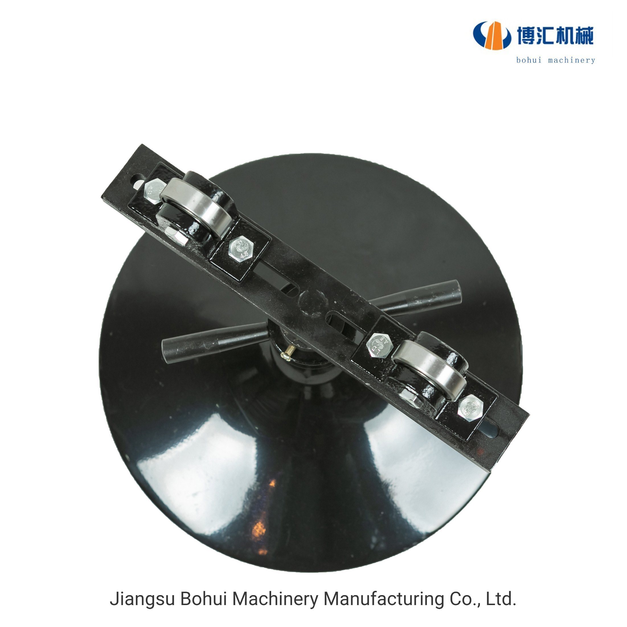
A rigorous pipe stand setup for welding ensures compliance and safety. You cannot rush this process. Following a standardized procedure protects your team and guarantees joint integrity.
Start by evaluating your workspace. Verify floor levelness using proper tools. Uneven floors compromise the vertical load path, pushing weight laterally onto the stand legs. Clear all debris, cables, and tools from the drop zone. Next, physically inspect the equipment. Check the stand locking rings for wear. Inspect the screw threads for galling or stripping. Examine the factory welds on the stand legs for fatigue cracks. Never load a compromised stand.
You must calculate stand spacing accurately. Proper spacing prevents the pipe from sagging in the middle. Sagging closes the root gap at the top of the joint and opens it at the bottom. Base your spacing calculations on the pipe schedule, total length, and material flexibility. As a general rule, place supports approximately two feet from each end. Add intermediate supports every eight to ten feet for standard steel pipe. Thin-wall exotic alloys may require closer spacing.
Set the base heights of all stands before loading the material. Lock the main pins in place. Use the micro-adjustment screw jacks to level the pipe precisely. You must follow a strict best practice here: never exceed the manufacturer's thread extension limits. Extending the screw jack too far introduces severe wobble. It dramatically increases the tipping risk. Keep the threads low and use the macro pin adjustments for primary height.
Loading requires clear communication between the rigger and the operator. Use proper slings to hoist the material. Lower the pipe onto the stands with extreme caution. Emphasize to your crane operators that the stand must never take a shock load. Dropping a multi-ton pipe even a few inches generates force that shatters cast iron locking rings. The load must transfer smoothly and completely before you remove the rigging.
The rules change entirely once you introduce movement. Managing static weight differs greatly from controlling dynamic loads. You must anticipate how the material will behave once the welding process begins.
Static weight means the pipe simply rests on the supports. Dynamic weight occurs when you manipulate the piece. When you turn a heavy spool on a Roller Pipe Stand, the center of gravity often shifts. Irregular spools, heavy valves, or offset flanges create an eccentric load. This imbalance forces one side of the pipe to push down harder while lifting the opposite side. Your supports must handle these sudden load transfers without buckling.
Standard gravity support fails when dealing with top-heavy configurations. If you weld a large offset flange, the pipe will try to roll off the stand. You must use hold-down devices to secure it. Hold-down rollers bolt over the top of the pipe, trapping it against the bottom wheels. Chain clamps offer another secure method. They wrap entirely around the diameter, locking the piece firmly to the stand base. Use these devices whenever the center of gravity extends past the vertical centerline of the pipe.
Continuous rotation introduces a problem known as longitudinal thrust. As the pipe turns on the rollers, slight imperfections in the pipe or floor cause it to "walk" or creep lengthwise. If left unchecked, the pipe will literally drive itself off the end of the stand. You manage this thrust in two ways. First, ensure perfectly parallel alignment between all roller stands. Second, use thrust rollers. These small vertical wheels mount on the sides of the stand. They press against the face of a flange or fitting to physically block the pipe from walking backward or forward during rotation.
Even experienced fabricators make setup mistakes. Recognizing common failures helps you build better risk mitigation protocols into your shop floor operations.
Over-extension remains the most dangerous setup failure. Operators often get lazy. Instead of adjusting the heavy main pin, they crank the screw jack to its absolute maximum height. This pushes the center of gravity dangerously high. The stand loses its rigidity, introducing wobble. Under a dynamic load, this over-extended setup easily tips over.
Mismatched materials destroy weld integrity. If you place a stainless steel pipe on standard carbon steel rollers, you invite disaster. Iron embeds into the stainless surface. This causes galvanic corrosion, leading to premature rust and NDT failure. You must mitigate this risk by swapping out standard heads for stainless steel sleeves or specialized urethane wheels when working with exotic alloys.
Uneven floor grades pose a significant compliance risk. Operators sometimes place wood shims under the legs of standard stands to level them. This practice violates safety standards. Shims slip under vibration, causing sudden load shifts. If your floor grade is uneven, you must upgrade your equipment. Switch to heavy-duty, self-leveling tripod bases that adjust individually to the terrain.
Guide your purchasing decisions using strict criteria. Never buy pipe stands based on upfront cost alone. Cheap, unrated stands cost more in downtime and safety liabilities. Evaluate stands based on third-party load certifications. Independent testing guarantees the unit performs to its spec plate under real-world conditions. Look for modularity. The ability to swap a V-head for a roller head on the same base saves money and storage space. Finally, demand a strong manufacturer warranty. Equipment built to handle heavy industrial fabrication should carry robust factory support.
Proper pipe setup represents a critical variable in welding quality control and shop floor safety. You cannot achieve perfectly aligned, defect-free welds if your foundation shifts, walks, or sags. By matching the right hardware to the job, calculating proper load distributions, and managing dynamic shifts, you eliminate the root causes of poor fit-up. Precision alignment protects your profit margins by drastically reducing NDT failures and costly rework.
Take immediate action to secure your fabrication process. Audit your current pipe stands to verify they carry visible load rating plates. Discard and replace any outdated or modified DIY stands that compromise worker safety. Before upgrading to commercial roller stands or alignment clamps, consult the manufacturer’s load charts to ensure the equipment meets your specific project demands. Standardizing your approach guarantees better welds and a safer working environment.
A: Safe weight capacities vary significantly by manufacturer and design. Standard units typically range from 1,000 to 2,500+ lbs. You must always check the manufacturer's spec plate attached to the stand. Never guess the capacity. Always factor in a 2:1 safety margin to handle unexpected dynamic load shifts.
A: No. V-head stands create extreme metal-on-metal friction. Rotating heavy pipe on a V-head damages the pipe surface, introduces gouges, and risks tipping the stand. You should use modular steel or urethane wheel adapters designed specifically to facilitate smooth, safe rotation.
A: As a general rule, place end stands approximately two feet from the pipe edges. Add intermediate stands every eight to ten feet for standard carbon steel schedules. You must place them closer together for thin-wall or flexible materials to prevent center sagging, which causes joint deflection.
A: A pipe stand acts as the primary load-bearer. It supports the physical weight of the material from beneath. An aligner is a precision clamping tool. It fits around the circumference of the joint to force two separate pipe sections into perfect concentricity, eliminating high-low gaps before tacking.